flowchart TB
subgraph Propulsion System
  Motor
  subgraph ESC
    Controller --controls--> INV-60V-120A
  end
end
ESC --drives-->Motor
1 Purpose
The purpose of this manual is to explain the operation to the user. The focus lies on the power electronics which is part of our Electronic Speed Controller (ESC)1. After reading this manual the user is able to design a control board which controls our power electronics. The ESC is still under development.
1.1 Liability
We shall not be liable for the slightly negligent breach of nonessential contractual obligations. In the case of slightly negligent breaches of essential contractual obligations, also if they have been committed by our legal representatives or our vicarious agents, our liability is limited to the foreseeable damage typical for the contract. Unlimited liability on our part exists for damages to body and health of the customer culpably caused by us, our legal representatives or our vicarious agents, as well as in the case of intent and gross negligence and for the absence of the guaranteed quality. If damage caused by slight negligence on the part of the customer attributable to us is covered by an existing insurance policy of the customer, our liability in the event of damage to property and/or financial loss shall be limited to the disadvantages for the customer associated with the claim against the insurance company. We shall not be liable for damage caused by improper handling of our products as well as improper influence of third parties on our products, improper assembly and/or installation, overstressing or overvoltage, unless these are due to our fault or a fault of our representatives or vicarious agents. The same applies in the event of unauthorised and improper repairs or interventions in the delivery item by the purchaser or third parties. We shall not be liable for damage caused by incorrect information and communications from the customer, unless these are due to our fault or a fault of our representatives or vicarious agents. We expressly point out that our motors, controls and other products have not been subjected to the safety and endurance tests prescribed for aircraft and aircraft equipment. We are therefore not liable for damage of any kind which occurs during and/or through the operation of our motors, controls and other products in/on manned aircraft, in/on aeroplanes, microlight aircraft, model aircraft, drones, rockets, hang-gliders and gliders, parachutes, air traffic control systems and any other type of aircraft. We are also expressly not liable for damages due to aircraft being grounded. We expressly point out that our motors, controls and other products are not approved for use in control systems of nuclear reactors. We are not liable for any kind of damage caused during and/or by the operation of our motors, controls and other products in control systems of nuclear reactors or in/at nuclear reactors. We are not liable for damages of any kind that arise from applications and use of our products that are subject to the German war weapons act. Our liability under the product liability act remains unaffected.
1.2 Scope of validation
This manual is only valid for inverters with the serial number INV-60V-120A.
1.3 Intented use
The area of validity is defined as act as the power electronics as part of a ESC. This ESC is placed inside a demonstrator. The following are considered improper use in the sense of a foreseeable misuse:
- using the power electronic in manned vehicles
- using the power electronic public vehicles and transport
- using the power electronic as a toy
- using the power electronic in potentially explosive atmosphere
- any use other than those provided for
1.4 Callouts
The following callout are used for signalisation.
Note for information purpose
Caution! This is warning! Possibility of damage to human life or machines
Very important information
2 System Overview
Figure 1 shows the location of the power electronics inside the system. It is part of an ESC, which needs a controller to be fully functional. Then, the ESC is able to drive a motor.
2.1 Communication
The power electronics offers a termination resistor for CAN bus. With a CAN-Transceiver on the controller board it is possible to use CAN.
2.2 Signalisation
The power electronic has three LEDs to signalizise states. Blinking patterns are described in Section 4.2.3.
3 Mechanical Specification
The power electronis are housed in an enclosure that contains a heat sink. This heatsink is essential to transfer the heat, generated by the power semiconductors, to the environment.
3.1 Housing
Housing
Potential hot surfaces!
Heatsink
The power electronic should be always be operated with a proper installed heatsink.
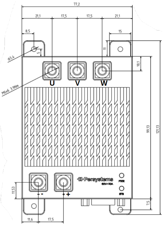
3.1.1 ESC top view
Dimensions are in \(mm\). The inner through holes are for M2.5, the outer through holes are for M3 screws.
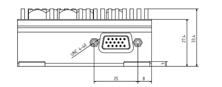
3.1.2 ESC front view
Dimensions are in \(mm\). The inner through holes are for M2.5, the outer through holes are for M3 screws.
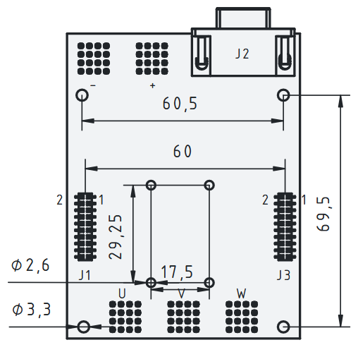
3.1.3 PCB
Dimensions are in \(mm\). The inner through holes are for M2.5, the outer through holes are for M3 screws.
| Connector | Type |
|---|---|
| J1 | Molex 79109-1209 |
| J2 | D-SUB15 female |
| J3 | Molex 79109-1209 |
The pin assignment of the D-Sub connector is standardized.
4 Electrical specification
The electrical interface can be divided into two parts. First, the power connection which connects the ESC to a power supply and a three phase motor. Second, the signal connection which consists of different signals.
4.1 Connection
For detailed information of the connectors refer to Section 3.1.3.
4.1.1 Power connection
Direction of power supply
Do not connect the power in reverse. This can lead to a permanently destruction of the power electronics.
Voltage limit
Maximum supply voltage is \(60V\)!
Current limit
Maximum current through the connectors is \(120A\)!
All terminals have to be connected with cable lugs with M6 through hole.
| Connector | Function |
|---|---|
| A | Motor Phase A |
| B | Motor Phase B |
| C | Motor Phase C |
| Power + | Power supply + |
| Power - | Power supply - |
The cable lugs have to be connected to the terminal with M6x8 screws with a maximum force of \(3.9Nm\)
4.1.2 D-Sub Connector (J2)
Table 2 shows the D-Sub 15 connections. A reference is added if there is are more complex circuit behind. if no reference is listed, the connection is a direct point to point type. Analoge ground (AGND) is supplied by the controller PCB. Ground (GND) is supplied by the main power supply and equal to Power -. The table shows also the initial purpose of the connection. The connections with a circuit should be used as inital envisaged. Other direct connections can be otherwise used.
| D-Sub 15 Pin | Direct Connection | Reference | Purpose |
|---|---|---|---|
| J2|0 | GND | ||
| J2|1 | Figure 5 | CAN low | |
| J2|2 | J1|8 | Motor temperature | |
| J2|3 | J3|5 | Hall W | |
| J2|4 | J3|6 | Hall U | |
| J2|5 | J3|4 | Pos sin | |
| J2|6 | AGND | ||
| J2|7 | J1|7 | CAN 0 | |
| J2|8 | Figure 6 | Enable | |
| J2|9 | J3|8 | Hall V | |
| J2|10 | GND | ||
| J2|11 | Figure 5 | CAN high | |
| J2|12 | J1|9 | PWM | |
| J2|13 | J3|12 | ||
| J2|14 | Section 4.2.3 | External voltage | |
| J2|15 | J3|3 | Pos cos |
The D-Sub connector is mainly used to transmit signals to or from the controller PCB.
4.2 Signal Paths
This chapter covers all relevant signal paths. Based on the notation of the connectors in the mechanical drawings these paths are explained further.
4.2.1 CAN
On the PCB there is already a termination resistor placed. The circuit is shown in Figure 5.
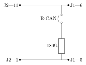
The jumper R-CAN should be inserted if the termination resistor is needed. The termination resistor value is set to \(180\Omega\). The standard \(120\Omega\) are used with twisted pair wires with known impedance of \(120\Omega\). The selected resistor value of \(180\Omega\) is more robust with different kind of wires. Another factor to consider is, that if the wire length is below \(l_{wire}<75m\) for a CAN bitrate of \(1Mbit\) the termination resistor do not have a significant influence. \[ l_{wire}<\frac{\lambda}{4} \] \[ \lambda_{CAN_{1Mbit}}=\frac{30000000\frac{m}{s}}{1000000\frac{1}{s}}=300m \] \[ l_{wire}<75m \]
4.2.1.1 Dronecan
Dronecan is implemented like specified on https://dronecan.github.io/ commit 601ed35 and is default set up for 1 Mbit/s Baudrate. 73 is set as default prefered Node Id and cam be changed via custom parameter. All uavcan.equipments.esc parts are implemented. Additionally there are following custom parameters available:
| Name | Min-Max | Notes |
|---|---|---|
CAN_NODE |
0 | preferred Node ID |
ESC_INDEX |
0-19 | can be used for position indication |
DIRECTION_INVERT |
0-1 | all setpoints inverted if true |
ZERO_SETPOINT_BRAKE |
0-1 | if true set ASC if armed but setpoint is zero |
OLS_USE_FASTSTART |
0-1 | exponential acceleration on open loop startup |
MOT_IMAX |
20.0-190.0 | maximum peak current limitation |
MOT_ISTART |
20.0-190.0 | while open loop forced phase current - depends on load |
OPEN_TO_CLOSED_LOOP_RPM_THD |
300-2000 | open loop to closed loop transition RPM threshold |
OPEN_LOOP_STARTUP_TIME_S |
0.3-5.0 | time to reach target RPM set up in OPEN_TO_CLOSED_LOOP_RPM_THD. Choose a higher value like 1.3 s if OLS_USE_FASTSTART is set to false |
ACC_RPM_PER_SEC |
1.0-50000.0 | acceleration in RPM per second |
RAWCOMMAND_MAX_RPM |
0-12000.0 | maximum RPM for raw command input to specify setpoint ratio |
FW_VERSION_LONG |
0-15151515 | read-only: firmware version, for example V01.02.03.04 |
4.2.2 Enable
Power
The buck converter needs a minimum voltage on the Power pins (Section 4.1.1) of \(16V\).
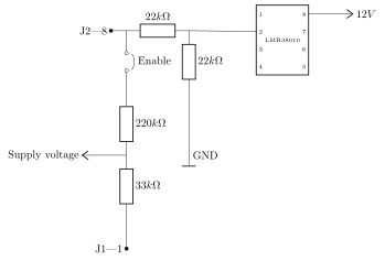
The enable is used to turn on the \(12V\) buck-converter of the board. This converter supplies the driver with the needed voltage. This enable signal can be provided by the pin J2|8 or it can be set to auto turn on with the enable jumper shown in Figure 6. The voltage of the enable pin(2) has to be greater than \(1.25V\). The output circuit of the buck-converter is simplified. As buck converter the LMR38010 is used.
4.2.3 LEDs
4.2.3.1 PWR LED
The purpose of this LED is, to automatically signalize a good voltage by a steady blue light.
4.2.3.2 STS LED (R/G)
| Color | Function | Pattern |
|---|---|---|
| R/G | firmware error - contact support | steady off |
| Green | Idle State STO/Freewheeling | 0.5 Hz blinking twice |
| Green | Controlling active or Active Safe State(ASC/STO) | 2 Hz blinking once |
| Red | Hard Fault see Error Messages via CAN | steady on |
5 Hard-Fault Handling
This describes the current application-level hard-fault handling.
A hard fault puts the drive into the fault state. For overcurrent, overtemperature, and unknown hard faults the driver is disabled, PPWM arming is cleared, and all user input setpoints are reset. If diagnostic CAN logging is enabled, the fault logger is triggered once for the latched fault.
Auto-recovery is handled in the 100 ms task. Recovery is allowed after 10 consecutive 100 ms ticks, i.e. about 1 s, if the fault condition is safe again:
- Overcurrent / unknown hard fault:
- trigger: phase peak current > 250A
- recovery: phase RMS current must be <= 3 A.
- Overtemperature:
- trigger: PCB temperature > 90°C
- recovery: PCB/inverter temperature must be <= 80°C.
- Overvoltage is mapped as a critical protection fault, but is not currently part of the auto-recovery list.
On successful auto-recovery, setpoints are cleared, control is stopped, target speed is set to zero, ErrorState is reset to STATUS_OK, and tries to re-enter control mode.
The fault logger is latched separately from auto-recovery. Auto-recovery can make the inverter operational again, but it does not acknowledge the logger fault latch.
5.1 DroneCAN Fault Mapping
If FOC open-loop handover failes at transition to closed-loop, it does not set a fault, but it triggers the diagnostic fault log and increments the DroneCAN ESC error event counter. uavcan.protocol.NodeStatus.health is derived from the current or latched internal ErrorState. uavcan.equipment.esc.Status.error_count increments when a new non-OK drive error is observed. The internal category is kept as firmware diagnostic state; vendor_specific_status_code is currently still 0.
| Internal state | DroneCAN NodeStatus health | Internal DroneCAN category | Notes |
|---|---|---|---|
STATUS_OK |
OK |
NONE |
No active fault. |
STATUS_PPM_INVALID, PPM_TIMEOUT, PPM_INVERSION_FAULT, PPM_SIGNAL_NOISY |
WARNING |
INPUT |
Input signal problem. |
| Missing motor constants / pole-pair info | ERROR |
CONFIGURATION |
Configuration is incomplete or invalid. |
| ADC offset calibration errors | ERROR |
CALIBRATION |
Calibration failed or is not valid. |
| Drive mode/control state errors, FOC init/state errors | ERROR |
CONTROL |
Control-path or startup failure. |
STATUS_OVERCURRENT_PROTECTION, OVERTEMPERATURE, OVERVOLTAGE |
CRITICAL |
PROTECTION |
Hardware/protection-limit fault. |
STATUS_INIT_FAILED, SOFTWARE_ERROR_UNHANDLED_ERROR, UNKNOWN_HARD_FAULT, default/unknown |
CRITICAL |
INTERNAL |
Internal or unclassified hard fault. |
6 Firmware Update process
The firmware update requires a PEAK CAN adapter and the PersyCAN Service application shown in Figure 7.
Connect only one inverter
Only one inverter may be connected to the same CAN bus during a firmware update. If multiple inverters are connected, a working application may be corrupted. In this case, the affected hardware must be reflashed by a specialist.
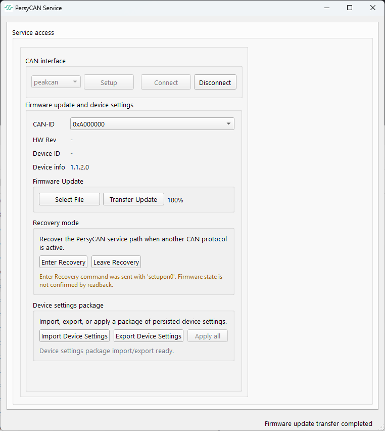
- Connect the PEAK CAN adapter and select
peakcanas the CAN interface. - Click
Setup, then clickConnect. - Check the
CAN-IDlist:- If an inverter is listed, select it and continue with the update.
- If no inverter is listed, it may currently be running the DroneCAN protocol. Click
Enter Recoveryand check theCAN-IDlist again. - If the inverter still does not appear, check the CAN wiring, termination, adapter connection, and power supply.
- Click
Select Fileand select the firmware update binary. - Click
Transfer Updateand wait until the transfer has completed. Do not disconnect the CAN adapter or remove power during the transfer.
DroneCAN after the update
If DroneCAN is configured as the default protocol, the inverter disappears from the CAN-ID list after the update has completed and the application starts. The installed firmware version can then be read from the DroneCAN parameters.
Footnotes
In this manual ESC and Inverter are equivalent terms.↩︎